Converting a plotted class of a project into a database table is no easy feat, or is it? For some cases it actually is surprisingly easy, that is why this topic will try and explain the process of converting classes to tables.
We want to convert classes to tables in order to actually start the transition from the planning phase to the executing everything planned phase. This is one approach that is in most cases advantageous for a project to take, and this process will help the software define actual data that it will need to run.
The most effective, straightforward and well known method to convert some diagram to a database or a data table is to make an Entity Relationship diagram. This diagram is a representation of data that can be found in a database, and since it is a diagram which has classes and their attributes, it is easy to make one grabbing some class diagram as reference. Converting the model of the software (or part of it) into an Entity relationship diagram has the advantage that it is fairly easy to convert into a table.
Components of the Entity Relationship Diagram:
There are three components:
- Entities: Number of tables you need for your database.
- Attributes: Information such as property, facts you need to describe each table.
- Relationships: How tables are linked together.
Entities and Attributes:

In the example above we can see an entity Relationship diagram. This diagram specifies its Entities (in gray), the entities’ attributes (in white) and their relationships with one another. If we see it from another angle, the “Class” will be our Entity and thus will turn into a brand new table, the class’ attributes will be, well, the attributes of the entities and therefore will turn into new columns for the entity’s table and finally the relationships which is the bridge in which they interact (also specifying how many of each entity can interact with one another at the same time).
Converting an entity relationship diagram into a table (or tables) will look something like this:
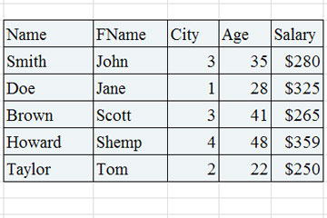
Relationships:
There are 3 types of relationships in this type of diagram:

One to One Relationship (1:1)
Means a single entity instance in one entity class is related to a single entity instance in another entity class.
For example:
- Each student fills one seat and one seat is assigned to only one student.
- Each professor has one office space.
One to Many Relationship (1:M)
A single entity instance in one entity class is related to multiple entity instances in another entity class
For example:
- One instructor can teach many courses, but one course can only be taught by one instructor.
- One instructor may teach many students in one class, but all the students have one instructor for that class.
Many to Many Relationship (M:M)
Each entity instance in one entity class is related to multiple entity instances in another entity class; and vice versa.
For example:
- Each student can take many classes, and each class can be taken by many students.
- Each consumer can buy many products, and each product can be bought by many consumers.
For the entity-relationship diagram to be turned fully (including these relationships which can turn a simple diagram to a complex problem) you need to follow a certain number of steps. This process is called mapping.
Here’s a brief summary of the steps that mapping follows in order to create its tables.
- Convert all the Entities in the diagram to tables.
All the entities in the diagram are turned into tables (of course being accompanied by their attributes).
- Key attribute in the ER diagram becomes the Primary key of the table.
Normally, an entity comes with a “key attribute” which is an attribute used to distinguish an instance completely from another instance of the same entity. This key attributes cannot repeat themselves in any way inside the table of its entity, making it essentially an identifier. When they are transferred to the table, they are renamed into “primary keys”.
- Declare the foreign keys.
This is where relationships take place to influence the table. In order to link two entities together because of a relationship, you need to define a “Foreign Key” column in one of the tables that is going to work as reference to the other entity’s primary key. This is to mark that there is a connection between a table and another.
Of course for step 3 there are other substeps to help you locate where do you need to declare the foreign key and how, according to the type of relationship that the entities share:
- For a one-to-one relationship, a foreign key can be held in either of the tables involved in the relationship, referencing the other table.
- For a one-to-many relationship, the table on the many side of the relationship should hold the foreign key referring to the one side.
- For a many-to-many relationship, you can create an association table (mapping table in your terms), which is a third table that holds foreign keys to both of the tables involved in the many-to-many relationship.
