Hello there! My name is Edgar, a student currently coursing computer science. I’m just getting this new blog going, so i’ll try to post information as i learn new stuff. Subscribe below to get notified when I post new updates.
Through the partial and well, all of the semester I learned about successful project management and the steps one could follow to develop as a developer. Being a developer is fun, but it is also filled with daunting tasks, requiring every bit of your strength and sleep hours to accomplish. That is why we as developers need to be great at either time management or working under pressure.
Yes, working under pressure is a skill every procrastinator must have and is a great advantage to complete tasks, but this skill has its limits and there are some things that cannot be done in a single day and have quality at the same time.
Organizing yourself is a very important part of being a developer. Especially because we are humans, and humans tend to make mistakes, organizing time can really help mitigating the time lost trying to solve a human mistake.
Through the semester, I felt really comfortable with the course since it takes into account the existence of other classes and lets us have more freedom in terms of deadlines. Even with the flexibility, just as everything must come to an end, the course needs to collect the work done in order to evaluate us. Deadlines, as much flexible as they can be, are inevitable. And so it was time to project in this blog what I learned about this past partial.
In the first 2 partials, through the masteries I learned how to plan ahead, how to execute the planning phase and convert it into the “doing things” phase and now, in this final partial, I learned how to check if everything went alright.
We learned about 5 different topics, but this time I only researched 3 (The importance of time management). At the end we as always tried to implement them in our real life project simulation. The topics viewed were:
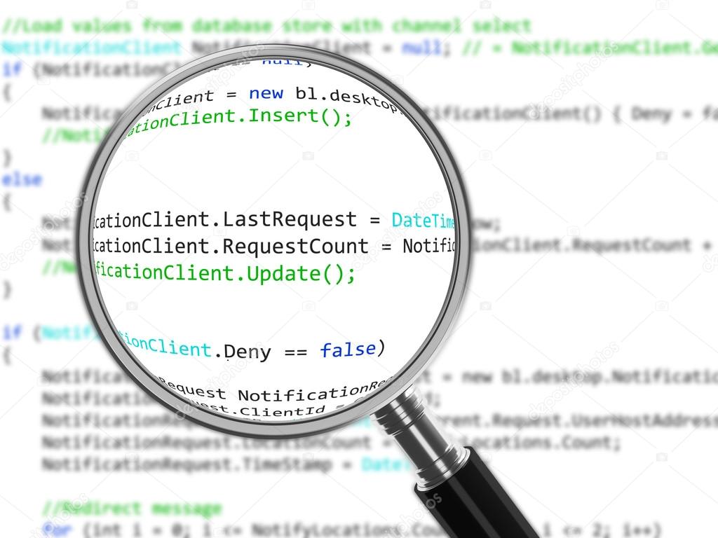
Code revision:
Code revision is something we may have all done in some point of time. It consists, as its name suggests, of reviewing code written in order to find mistakes, errors or bugs. This is a very important step in coding and it then has to preferably be as effective and efficient as possible. That means there must be some kind of practices in order to efficiently review code.
Verification and Validation is the process of investigating if a software satisfies specifications and standards, it makes sure the software can complete the tasks it was intended to do.
Verification is the process of making sure the software verified can do the tasks imposed without any bugs. This can be resumed in making sure it has no errors, no weird bugs and functions as it should
Validation is the process of making sure that the software can actually fulfill the requirements imposed to it. It is the process of checking that the software created is actually the software we want or need.
Object-oriented testing (or OOT) is a collection of testing techniques to verify and validate object-oriented software. As we all probably know, testing is a crucial part in the development of a project, and if we don’t do it effectively we will be left with a high chance of having a buggy code, or a non-optimized program or one that doesn’t even work at all.
I personally find myself unit testing a lot, which is a kind of object oriented testing.
The final part of the project was completed! This was the wrapping up of the investigation and planning phase, we were asked to make a video of ourselves explaining it and giving our personal views about it. We also were asked as always to write a document with our advancements. The final steps were receiving feedback and adjusting the system to fulfill the new requirements of the stakeholders.
We received some feedback from each stakeholder, majorly it was positive, but there was one person who changed the perspective of our project entirely. This person is in charge of giving us knowledge on the “hardware part” of the project, meaning he was selected to give us advice in the type of sensors, how many would we need and how could they power themselves up. After hearing what we have done, he proposed reducing the number of sensors, since it would be a very resource and money expensive thing to do, he suggested for the sensors to be in an area, checking the cars that go in and go out of it. This would greatly reduce the number of sensors needed.
As we were focused more on software development and not to worried about hardware, this fault completely missed us and we did not realize how difficult of a task it was for each sensor to work properly for an extended amount of time. Since our project was focused on organizing the software part of the project, the changes we did were not that big, but it was a really good observation from that stakeholder.
For the time I’ve been in this course I think I have grown to be more responsible and more aware of time management. I feel like I have the ability to learn in my own now, thing that is very important in order to succeed. I understood that a developer doesn’t just sit in a chair and writes code. It is not just receiving a request and immediately jump to your computer to start coding. A developer has to plan ahead, socialize, organize himself, receive feedback and react accordingly. Like most projects in life, software development consists of planning, executing, and getting feedback, and you may not succeed in every plan, but being passionate of what you are doing , organizing yourself and never giving up is the key to success.
Object-oriented testing (or OOT) is a collection of testing techniques
to verify and validate object-oriented software. As we all probably know, testing is a crucial
part in the development of a project, and if we don’t do it effectively we will
be left with a high chance of having a buggy code, or a non-optimized program
or one that doesn’t even work at all.
OOT are techniques designes specifically to better test object
oriented programs, but not all of the extensive testing needs to be done , just
parts that you see fit, which is why it will be explained here.
Of course testing is seen mostly in the final stages of a project,
but these tests will put in observation every aspect of it. There are several
aspects that need to be tested, we can represent them with the image below.
How to test:
There are different types of tests as stated avobe, but the
different testing procedures can be classified into three main categories:
Unit Testing: In unit testing, since it is object-oriented, we can separate each class by its own and test its functionality. This can tell us errors in the input output logic or in the interface environment. Since it is separated from other classes, it becomes a lot easier to spot logical problems.
Subsystem Testing: This testing procedure involves testing a group of classes together (or a subsystem). This test focuses on the relations between classes, as well as the interaction with the system outside the testing subject.
System Testing: This testing involves the whole system (as its name says). This test procedure takes in responsibility the quality of the system as a whole.
Tips and Tricks when testing:
Don’t forget, the goal is to find defects. The focus of a test is to validate the correctness of the functioning of your classes. Finding bugs in the testing phase is better than finding them in the final release.
You can validate all code. You can test all your assets in the project; do not just limit yourself testing the source code. It is not often but mild errors can occur in this part too.
Test often and early. The longer it takes to find a bug in the development stage, the greater the cost to be able to correct it.
Test to the risk of the module. The riskier something is, the more it needs to be reviewed and tested. In other words you should invest significant effort testing in an air traffic control system but not that much effort testing a “Hello World” application.
One test is worth a thousand opinions. Same thing as one action speaks for a thousand words, showing a successful test result is far more valuable than just saying that it works.
Verification and Validation (or more commonly
known as v&v) is the process of investigating if software satisfies specifications
and standards, and also makes sure the software can complete the tasks it was
intended to do.
Although they come together, verification and
validation are two very different things.
Verification is the process of making sure the software verified can do the tasks imposed without any bugs. This can be resumed in making sure it has no errors, no weird bugs and functions as it should
Validation is the process of making sure that the software can actually fulfill the requirements imposed to it. It is the process of checking that the software created is actually the software we want or need.
A very short but very precise description of
both validation and verification provided by Barry Boehm is:
Verification: Are we building the product right?
Validation: Are we building the right product?
These are very powerful phrases because it
actually just summarized all of the above.
Procedure:
To verify and validate there is a common,
pretty general but recommended procedure to follow. The Verification has to be
followed by the Validation. Meaning we first verify if our software actually
works and then we validate that our software is actually useful.
This also means that it is entirely possible
for a product to pass the verification procedure but fail de validation
procedure, rendering the product unfinished. This can also happen even if the
software is built according to the specifications given, but still failing to fulfill
the user. In other words, the user has the final word in a project, as I think
it should be.
Verifying and validating both are executed by the use of tests to the software.Testing is a core part of the developement of a product, but one must know what tests must be done in order to ensure quality. Below there is a chart with tests belonging to either verification or validation. You may have heard of some of them before:
chart of tests belonging to verification or validation
To verify and validate properly there are standards
you would want to follow, meaning there are standards for quality control in
software as well. These are called Quality management systems (QMS) and are a
great tool to meet the necessary requirements in order to have a global
acceptance. For example the Institute of
Electrical and Electronic Engineers (IEEE) has one standard with procedures
and, well, explanations (this standard is called IEEE 1059). However access to
this document is behind a paywall.
Another standard is the ISO 9001, this one is
actually free and can get a project (or organization) to meet global standards
in terms of verification and validation.
Below I leave a link to the ISO 9001 guide and
materials download page:
Code revision is something we may have all done
in some point of time. It consists, as its name suggests, of reviewing code
written in order to find mistakes, errors or bugs. This is a very important
step in coding and thus it has to be preferably as effective and efficient as
possible.
There are many tips and tricks to maintain an
efficient code revision, but I think there are two main advices every
programmer should take.
Reviewing a lot of code in one sitting tends to be a bad idea, especially when the code is confusing or extensive. The recommendation is to review in parts; no more than 400 lines per hour should be reviewed. This is to maintain focus and being effective at it. Also it is recommended to take rests between revision hours for the same reason.
Being organized is imperative in code revision, especially if the code does not do what it’s intended to or if the code has a bug which its origin is hard to tell. A method to have this point in check is to have completion lists, also known as milestone or to-do lists. Keeping everything in check, signaling observations, test results or stuff that has not been done yet can greatly improve the revision time and effectiveness.
A powerful and very convenient tool to have if everything decides to go south is revision control, also known as version control or source control. This tool manages changes made overtime not limiting itself to source code; it can also manage assets and metadata. One example of this almighty tool is git (I use Github). It manages a repository in which you can upload any project, it will have in check every upload version you give it and even can branch itself to have different versions, not just in a linear way.
Putting this into practice will improve
revision time and maybe lessen the headaches a project may give. Also if you
have revision control, it becomes easier to compare versions of the same code
from when it was working properly. The only downside I can see is not even a
big one. Being organized about a project development requires effort, but I think
the effort put into documenting, marking or making a to-do list is much lesser to
the effort put to debug a spaghetti code or code only god knows how it works
since everyone forgot.
In this partial I did not have the opportunity to assist to
class very often, primarily due to work and family needs. But this is not to
worry because I still learned a lot through the making of masteries and
listening to the few classes I went to.
In one of the classes a meeting was held for us with an
important person, this person talked about his experiences in job interviews,
about how it is working for a company and how he got a really high position in
his job. He told us he went to meetings every time he could, volunteered in
technology events, and made himself known in order for others to consider him
while searching for employees.
In this time I learned that if I want to be a successful
person as a developer, it is not enough to just be super good in programming or
the developing process. You also have to make yourself known amongst the
community by either applying for jobs, volunteering in events or just writing
blogs in the internet.
As always, below there’s a resume of what I learned or have
seen this partial.
Design patterns:
It is not an exaggeration when people say that design patterns
are REALLY helpful. They are a great invention of humanity designed to help us
developers in times of need. They help speed up the development process. They
provide an already proven solution to any problem you could have! (Of course
only if someone else encountered the same problem and actually wrote a design
pattern for a solution to it. But most likely there is). Design patterns save
us a lot of time in debugging code because they consider issues or bugs that
often won’t pop up until later in development, which may happen with fresh code
not following a design pattern. Also they add readability for someone who also
is familiar with them. They are kind of like a common ground for us developers
to actually understand something out of our spaghetti code.
UML:
The Unified Modelling Language (UML), if you are a software
developer it will become a great ally. It is a really flexible tool to create understandable
diagrams, and its clearness is not diminished even if there’s a massive
difference between diagrams created with it. Even better, formal notation of
UML is not even necessary in order to understand it; this is because UML likes
to keep things general, easy to understand and not necessarily complex in structure.
Another massive advantage you will have if you decide to learn UML is that this
modelling language is very popular. A lot of people will actually understand
your diagrams and what you want to transmit. It would really be a shame if the
“universal” modelling language wasn’t as popular, so good thing that it is.
Currently there are around 14 different types of UML
diagrams. Every diagram is focused in showing a different part or different
information of a system. We should familiarize ourselves with the different
types and stick them to future projects. UML is a very useful tool.
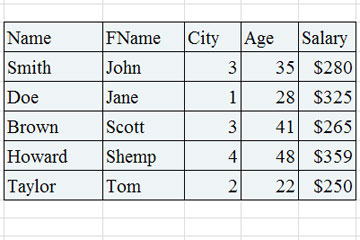
Converting classes to tables:
Accurate representation of a table
Converting classes to tables is a common thing to do in a
project environment. We want to convert classes to tables in order to actually
start the transition from the planning phase to the executing phase, or the “make
a database for this” phase. This is one approach that is in most cases
advantageous for a project to take, and this process will help the software
define actual data that it will need to run.
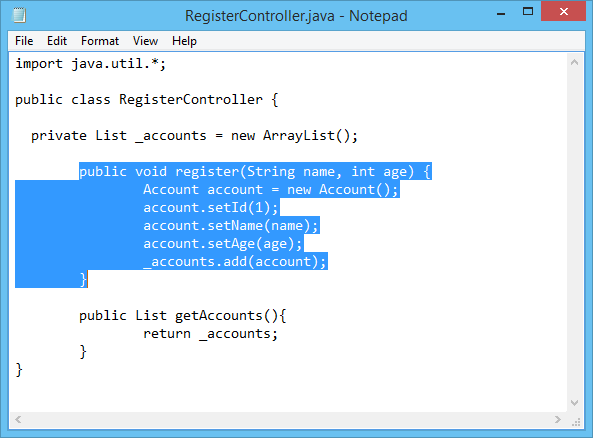
Converting classes to code:
Accurate representation of a code
Converting classes to code is even more common than
converting classes to table, or that is what I think. This process marks the
start of the executing phase, alongside the conversion to tables. It is fairly
easy to do since all the logical planning is kind of already done. The only
thing left to meditate about is deciding into what language are you going to
translate your diagram to, and if it is a non-object oriented language, perhaps
some extra steps will be necessary. Deciding
what is the best language to code the software is very important to translate a
diagram. Yes technically all languages are capable of just about the same thing
but some of them will make the software run faster or be optimized in certain
situations, and the most important point, the implementation can be a lot more
difficult in one language than in another.
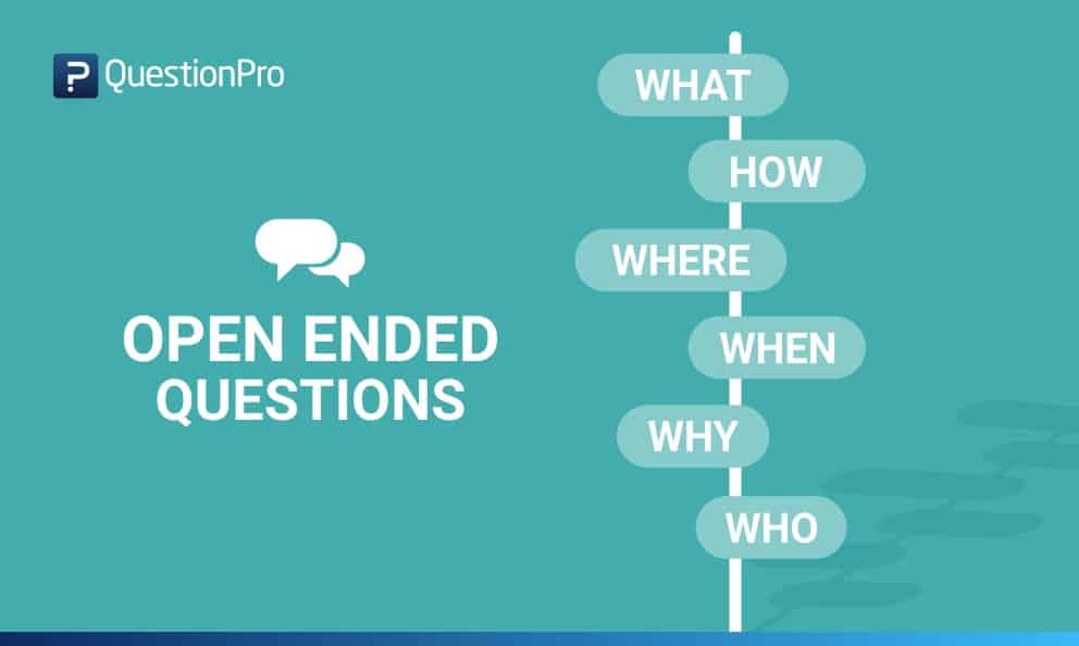
Project update:
Accurate representation of stakeholders answering crucial questions
In this part of the project we focused in doing interviews
to the stakeholders, gathering their hopes and dreams. We use that information
to improve our project model, define user stories and improving our use case
diagram. What I learned about this part of the project, and consider that this
could be a useful trick to interviewing for a project in the future, is that
when asking questions to stakeholders it is very important to let them express
their thoughts with open questions. It is a really bad idea to just ask yes /
no questions because then information can and will be omitted that could be
important for development and no one will know about it until it’s too
late. If it is inevitable to ask a yes
or no question, then asking the reasoning behind the answer too is the best
approach since, for the project, is very useful to know the thought process and
perspective of each person involved in the project and making it easier to
fulfill their expectances or to collaborate.
In the project, we proceeded to do just that. Try and ask
open questions or tying to ask the reasoning behind a closed one. We also tried
to avoid vague responses by asking precisely. I would also recommend that.
Asking generic questions can often lead to generic and vague answers, so it is
better for it to be as precise as possible.
Next in the list was updating the user history and starting
making diagrams. First comes interpreting the interviews, for this part, the
difficulty of the task depended on how consistent and precise was the answer
for each individual. This was not difficult for our team because I consider we
asked the correct things. After the making of the user history we started with
the user-cases and the user-case diagram. Then finally we started creating the
other diagrams relying on the user-case one.
For this project we made a class diagram, an object diagram and a state
diagram, we thought we could work with those to create a mock for our final
software to see what reaction it would get for our stakeholders.
The next step for us is to present our work done to the ones
involved in the project and receive feedback. Once adjusting the observations
done, the project would then technically theoretically be ready to start the
implementation process.
For the time I’ve been in this course I have realized how
much I can learn in my own, and that self-teaching is a really powerful skill
people can have in order to advance in life. When I say ability, it may sound
as something that some people may not be able to achieve, but this is not true.
I believe everyone can learn how to learn by themselves, it is a combination of
searching skills, practice and perseverance. Of course you also need interest
in the subject. But I encourage anyone to try and take the path of learning on
their own.
Making diagrams while developing a project is
really useful, it helps connect ideas, shows a clear way of the architecture or
the behavior of the various systems and they will become kind of a guide at the
moment of coding the project. But at te end of the day diagrams are just
diagrams, a pretty picture. What it is important is the value given to it and
what useful information is put to it. In other words various diagrams will have
different importance at the time of actually starting to code something. This
really depends on your approach in choosing the language of implementation,
libraries to be used or maybe databases or services to be created.
That is why this blog will attempt to explain how
is the process of collecting data shown in diagrams and actually implementing
it it’s done.
UML Diagram
Code made from interptreting an UML Diagram
Choose your tools:
Deciding
what is the best language to code the software is very important to translate a
diagram. Yes technically all languages are capable of just about the same thing
but some of them perhaps will make the software run faster or be optimized, and
the most important point, the implementation can be a lot more difficult in one
language than in another.
Some things to consider:
While it is important to consider the efficiency
a language can bring to the table before others, it is also recommended choosing
one that you are familiarized well enough with. Otherwise yes, maybe it will be
efficient and in better state but the time to code it will raise a lot more
than if you code it with something well-known or, because of the inexperience with
the language, the program will turn out buggy or even inefficient. Do not misunderstand
in allways choosing the language you know best, just choose from the ones you
kind of know about.
Familiarize yourself with what the diagram
means, the difficulty of translating a diagram into code varies a lot between
projects and developers, one criteria being the understanding of the software
to be implemented and the things it will require.
Finally don’t be afraid of potential mistakes, when translating a diagram
to code a lot of common logical mistakes are avoided already, the ones left
will be easier to solve than if the code was made without planning first. The
errors that will occur during the implementation will be eventually solved.
Diagrams to a non-object oriented language:
Lots of diagrams in UML tend to direct
themselves to an object oriented environment. But worry not because translating
diagrams can also be done into a non-object oriented language. UML diagrams or
well object oriented diagrams tend to represent two things off of software: The
architecture (how it is made or what are its components) and its behavior (what
will it do or how will it interact). Meaning objects, while recommended, are
not entirely necessary to the process. You just have to pay attention to the
requirements of a system and how would it behave.
Converting a plotted class of a project into a database
table is no easy feat, or is it? For some cases it actually is surprisingly
easy, that is why this topic will try and explain the process of converting
classes to tables.
We want to convert classes to tables in order to actually
start the transition from the planning phase to the executing everything
planned phase. This is one approach that is in most cases advantageous for a
project to take, and this process will help the software define actual data
that it will need to run.
The most
effective, straightforward and well known method to convert some diagram to a
database or a data table is to make an Entity Relationship diagram. This
diagram is a representation of data that can be found in a database, and since
it is a diagram which has classes and their attributes, it is easy to make one
grabbing some class diagram as reference. Converting the model of the software
(or part of it) into an Entity relationship diagram has the advantage that it
is fairly easy to convert into a table.
Components of the Entity Relationship Diagram:
There are three components:
Entities: Number of tables you need for your database.
Attributes: Information such as property, facts you
need to describe each table.
Relationships: How tables are linked together.
Entities and Attributes:
Entity Relationship Diagram
In the example above we can see an entity Relationship
diagram. This diagram specifies its Entities (in gray), the entities’
attributes (in white) and their relationships with one another. If we see it
from another angle, the “Class” will be our Entity and thus will turn into a
brand new table, the class’ attributes will be, well, the attributes of the
entities and therefore will turn into new columns for the entity’s table and
finally the relationships which is the bridge in which they interact (also
specifying how many of each entity can interact with one another at the same
time).
Converting an entity relationship diagram into a table
(or tables) will look something like this:
Relationships:
There are 3 types of relationships in this type of
diagram:
One to One Relationship (1:1)
Means a single
entity instance in one entity class is related to a single entity instance in
another entity class.
For example:
Each student fills one seat and one seat is assigned to only one student.
Each professor has one office space.
One to Many Relationship (1:M)
A single entity
instance in one entity class is related to multiple entity instances in another
entity class
For example:
One instructor can teach many courses, but one course can only be taught by one instructor.
One instructor may teach many students in one class, but all the students have one instructor for that class.
Many to Many Relationship (M:M)
Each entity
instance in one entity class is related to multiple entity instances in another
entity class; and vice versa.
For example:
Each student can take many classes, and each class can be taken by many students.
Each consumer can buy many products, and each product can be bought by many consumers.
For the entity-relationship diagram to be turned fully (including
these relationships which can turn a simple diagram to a complex problem) you
need to follow a certain number of steps. This process is called mapping.
Here’s a brief summary of the steps that mapping follows in order
to create its tables.
Convert all the Entities in the diagram to tables.
All the entities in the diagram are turned
into tables (of course being accompanied by their attributes).
Key attribute in the ER
diagram becomes the Primary key of the table.
Normally, an entity comes with a “key
attribute” which is an attribute used to distinguish an instance completely
from another instance of the same entity. This key attributes cannot repeat
themselves in any way inside the table of its entity, making it essentially an
identifier. When they are transferred to the table, they are renamed into
“primary keys”.
Declare the foreign keys.
This
is where relationships take place to influence the table. In order to link two entities
together because of a relationship, you need to define a “Foreign Key” column
in one of the tables that is going to work as reference to the other entity’s
primary key. This is to mark that there is a connection between a table and
another.
Of
course for step 3 there are other substeps to help you locate where do you need
to declare the foreign key and how, according to the type of relationship that
the entities share:
For a one-to-one
relationship, a foreign key can be held in either of the tables involved in the
relationship, referencing the other table.
For a one-to-many
relationship, the table on the many side of the relationship should hold the
foreign key referring to the one side.
For a many-to-many
relationship, you can create an association table (mapping table in your
terms), which is a third table that holds foreign keys to both of the tables
involved in the many-to-many relationship.
Deepening the subject of UML, there are a lot
of available types of diagrams in UML, each serving a different purpose even if
some of them look similar to each other, they have their own characteristics
and cases of use.
In order to continue viewing the different
types of diagrams UML has to offer, this blog will contain 3 more types:
State diagrams.
Package diagrams.
Component diagrams.
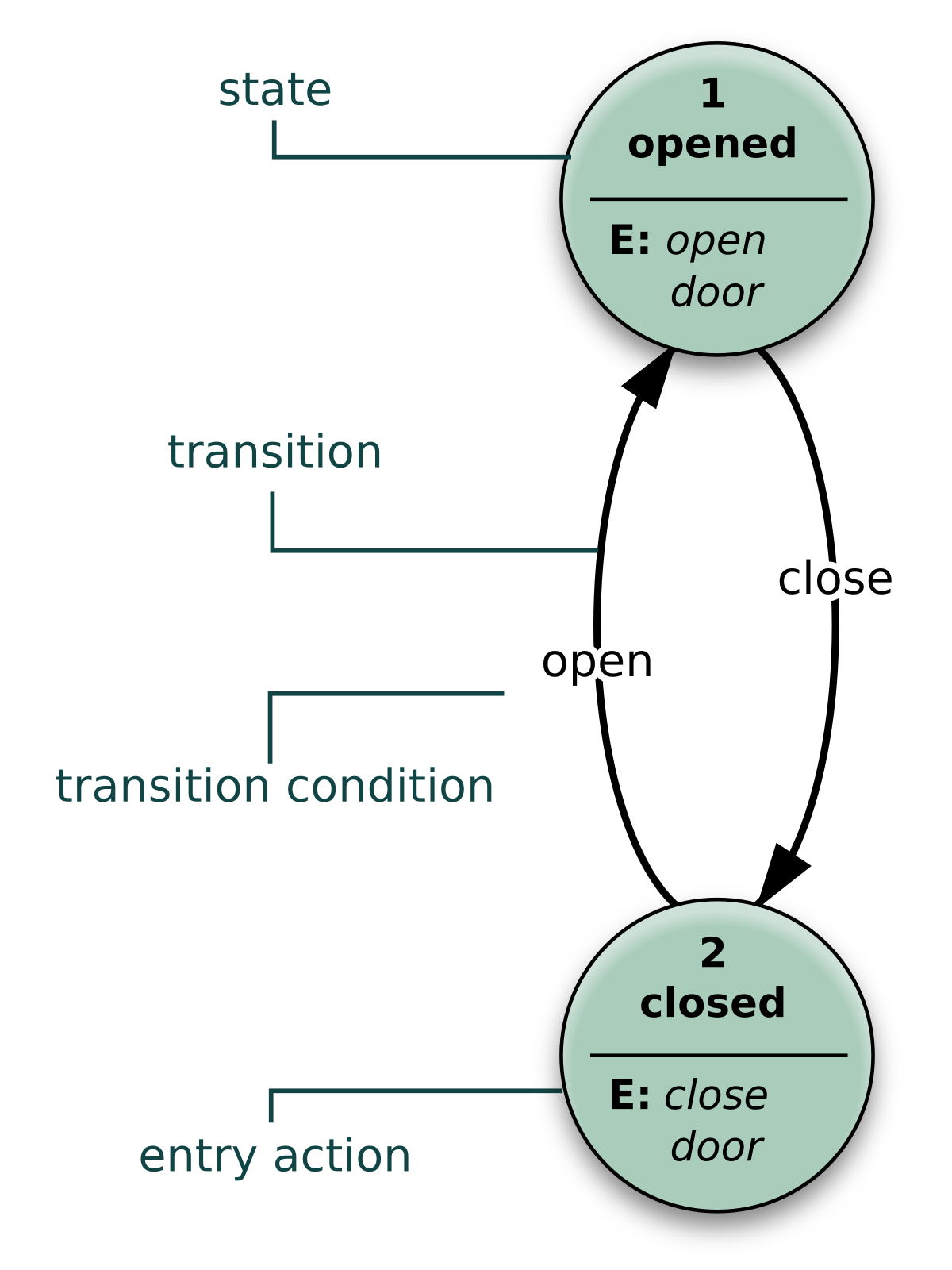
State diagrams:
Example of a state diagram
A state diagram represents the condition of a
system at a certain time, similar to the previously seen object diagram, but there’s
a key difference which makes them very appar from each other. While object
diagrams show the structure of a system at a particular moment in time, a state
diagram will show us the condition of the system, here it will show us what is
it doing or it is supposed to do, instead of just showing what’s inside and
what objects relate to one another.
This diagram helps us really well in
understanding the reaction of objects to whatever input it receives.
Package diagrams:
Example of a package diagram
Package diagrams, alongside object diagrams are
of the structural type of modeling languages. It shows the arrangement and
organization of a project, hence why is called package diagram. It can show the
structure and the hierarchy of systems and subsystems, perfect for evaluating a
multi-layered application.
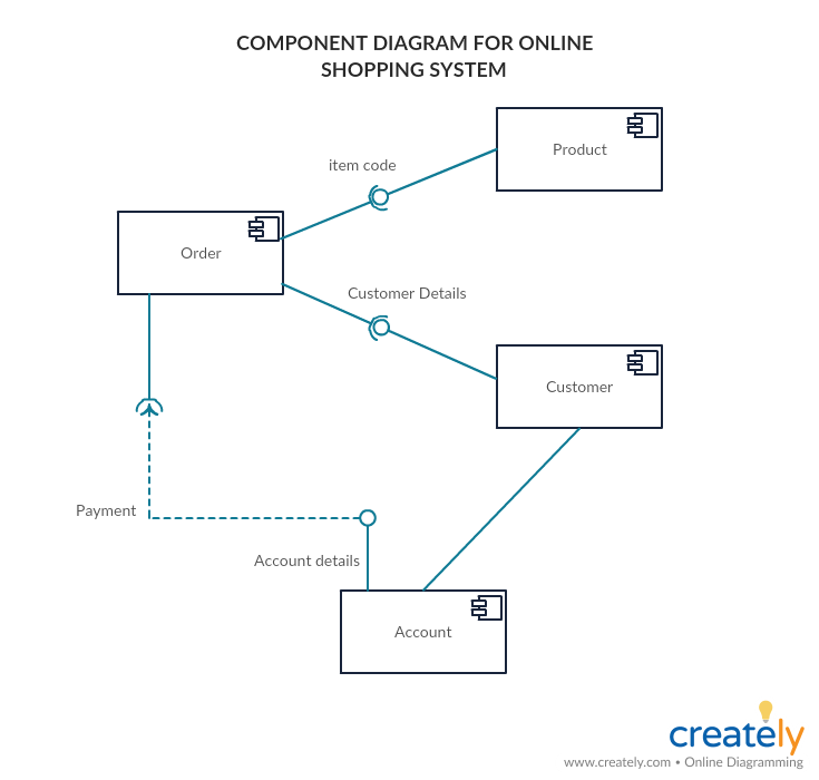
Component diagrams:
Example of a component diagram
Component diagrams, as its name suggests, shows
the different components and their relationships within a model. This sounds
very similar to Class diagrams, but it is not. While they are trying to
accomplish a similar goal, a class diagram is a lot more precise and “low level”
than a component diagram, you use this one when classes are not well thought
yet or when things are still a little fuzzy at the beginning of a project, a
component in a component diagram can generalize some interaction with closer classes,
which is why this diagram is advantageous to be done at the beginning of a
project.
What is GRASP:
NOT THIS KIND OF GRASP
GRASP stands for “General Responsibility Assignment Software
Patterns”. It is a conjunction of coding patterns that help us develop
or model a project, correctly delegating responsibilities to the correct
classes in order to create the best software possible. If you want to create good
software with good coding patterns, you will have to start by using design
patterns in your modelling and software design phase too.
GRASP cosnsists of 9
design patterns:
Information Expert 2. Creator 3. Controller 4. Low Coupling 5. High Cohesion 6. Indirection 7. Polymorphism 8. Pure Fabrication 9. Protected Variations
This concludes the introduction of UML. in summary, we can use UML in various advantageous ways thanks to its flexibility and easyness. Furthermore there are a lot of diagrams that fall into the UML domain making it very complete and also making it the holder of any tool we might need in order to design anything.
The unified modeling language or better known as UML is a modelling
language, best known for its easiness of use and well, that everyone uses it
over all other modelling languages.
A UML Class Diagram template
UML is a standard created to unify (as its name says) lots of modelling
languages out there, which complete different tasks, or are actually good in
some aspects. UML therefore tries to excel in basically every task possible for
a modelling language. This gave as a result a really extensive, easy to
understand and flexible language everyone (but mostly developers) can use.
Why we use UML
The Unified Modelling Language as stated before is really flexible, and
its clearness is not diminished even if there’s a massive difference between
diagrams created with it. Even better, formal notation of UML is not even
necessary in order to understand it; this is because UML likes to keep things general,
easy to understand and not necessarily complex in structure.
Another huge advantage of UML over other modelling languages is its
popularity. When talking about these languages, often what people think as an
example first is UML, it is really popular around the world, it would really be
a shame if the “universal” modelling language wasn’t as popular, so good
thing that it is. Because it is well-known, it provides a common ground for
developers for them to show, explain or understand systems, hierarchies or how
the software will work.
Currently there are around 14 different types of UML diagrams, in this
we can see how diverse can it get, but in this entry we will see 3 main types:
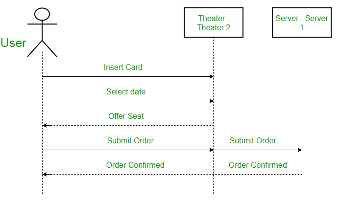
Sequence diagrams:
A sequence diagram showing the process of buying theater tickets
A sequence diagram shows the interaction between the objects in within
some software in the order that the objects execute their interactions. Another name for these diagrams is event
diagrams. They are useful to describe in what order the objects will interact
with each other and how will they do it. Now these diagrams work especially
well for developers in order to understand how the software will work and
define system requirements whether defining new ones or refreshing the old ones.
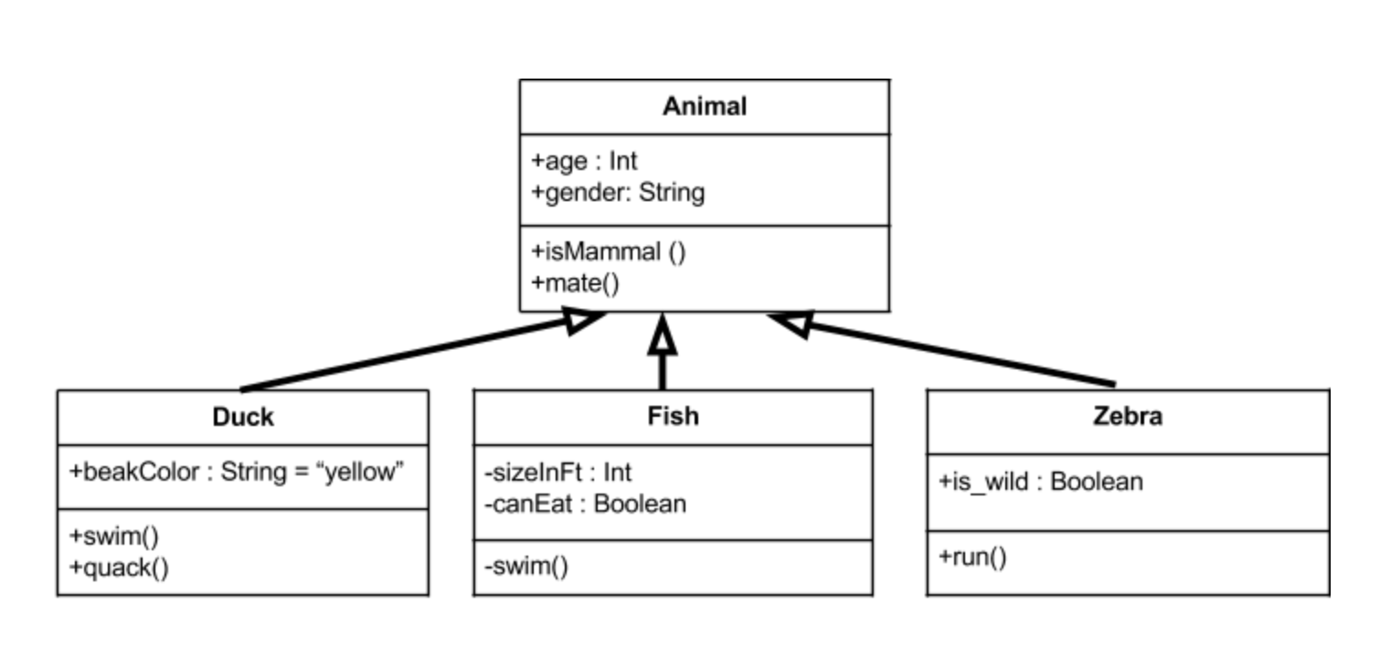
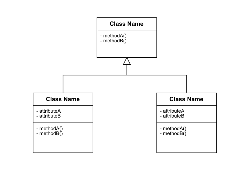
class diagrams:
Class diagram of animals
A class diagram shows the
structure of some software by showing its classes and their components; this
means their methods, attributes, heritage etc. It also shows how these classes
can interact with each other; the difference with the above is that it won’t
show how they interact exactly or at which moment. It is kind of like a visual summary
of a system.
We can use them to project the
system as it is currently in the different phases of development to gain a big
picture of the software.
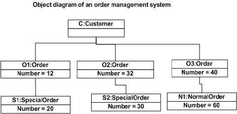
object diagrams.
An object diagram shows the
structure of the software, kind of like the class diagram, the only difference
is that just as objects derivate from classes, an object diagram derives from
the class diagram. The object diagram is an instance of a class diagram,
meaning it shows the structure of the software at a specific moment of the
program, showing the current relations and the values of the attributes.
It is really useful for moments
when the software has to be tested, or to verify that it is actually working
correctly.
UML is really useful and flexible,
you don’t really need to learn it, but you should check it out because it can
really be a very helpful tool in your arsenal.
This partial I learned a lot about project managing and
personal growth. There is more to being a developer than just knowing how to
write code.
In the partial, our teacher Ken lets us have a flexible schedule
when it comes to deadlines, and the class focuses more on talking / discussing
about a topic than to just read about it or having the professor to explain
everything at his own pace risking some students to fall behind. I think that
this flexibility and discussion classes are pretty useful for everyone, it
permits learning the content of the course at each student’s own pace, and
because of this flexibility we as students can focus on other projects and
still have time to focus and actually learn about the course topics in the
given time.
Throughout this time period we learned about 4 different
topics, and in the end, implement them in a real life project simulation, which
is our class project. These are the topics viewed:
Software life cycles:
Software life cycles are kind of like plans to help the
development of a project; each life cycle specializes in some aspect of the
development or takes it with different approaches. They may not seem really
important in small projects, but it is almost imperative to have in bigger ones,
mostly because it is really easy to get lost when continuing throughout
development, adding and scrapping ideas, a change of plans, or some sort of
unseen error. Without one, it becomes more likely to forget or bypass crucial
information previously stated or to just not managing time in order to finish a
project.
Software life cycles are more about time and resource
management and they are a difference between a meh result and an outstanding
result.
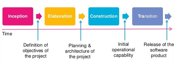
Unified software processes:
This “Unified software process” is like a form of planning a
software development ahead based on the user’s expectations. Following this
process will lead to the act of determining how will the software will be
built, what resources will be needed in order to satisfy the end users.
The process divides itself in some steps: firstly takes in
account feedback or expectations from stakeholders or people involved in the
software, forming requirements for the end product. Then a software plan is
made so it satisfies the previous requirements. The software then is built and
finally it is given feedback.
The process is iterative and incremental; meaning the
previous series of steps can be performed as much as we want in order to make
the best software possible.
Use cases:
In my experience, use cases will be present a lot in
software development. There has been around 5 projects I’ve done in the last
year. All of them contained use cases, or use case diagram.
A use case is a really helpful tool that will help us
organize the different kinds of interactions the software will have with
different users, other components or with the admins. We create a use case for
someone when we want for that someone or something to interact with our
software. It is basically a list of things that we need to take in account when
starting development stages.
From these use cases we can create something perhaps more
useful for the human eye instead of a list, we can create a use case diagram.
These diagrams in my experience with projects are extremely
useful when planning how some software will behave and when creating other
diagrams like a class diagram. With these we can easily know who or what will
want to interact with the program.
Modeling Languages and Tools:
Modeling languages will actually help us understand or
picture relationships, classes and interactions of a software that would
otherwise be a little too complex to remember or to put in a list. This models
are a visual aid for developers or well, people involved in the project. A very
good example of a modeling language is UML which is really useful for
developers in my experience. Modeling languages, like any other language, have
their own set of rules and context, and thus many modeling languages exist.
Some of the main examples of this are:
System modeling language
Object modeling languages
Virtual reality modeling language
Data modeling language
Some of these topics may look similar to each other, but
each one has their own differences and serve different purposes.
Pharo resume
Throughout the course, the class has this “side quest” which
we can complete only for personal growth purposes. The task that was given has
to do with auto-learning. We were tasked to learn a new programming language
called Smalltalk, this is because it is designed to be purely object-oriented.
Inside Smalltalk everything created will be an object, from self-created
classes to just plain numbers. Learning about this language will help us
understand or work out our thinking focused on object oriented programming. It
was difficult at first because although the Virtual machine we use to program
in this language (Pharo) comes with a tutorial explaining data types, how
methods and classes work, parameters etc., it still didn’t explain things that
much clearly or completely, this wouldn’t be a problem since we have the
almighty internet guides, but very often it will encounter outdated information
which doesn’t work anymore.
Once I got the hand of it, I started to recreate some of my
past projects orr programming excersices in this language as practice, it was
very useful to star knowing about pharo and smalltalk. It forces yu to think
differently.
Below I leave a link which has some knowledge I gathered by
working with Smalltalk.
Currently I am doing a software development project
simulation alongside some classmates. This simulation is focused on learning
how a real project would look like. We will need to, at some point, implement
the knowledge found in the other blog posts.
Our project is about implementing a solution to parking in
our campus, since our school has this problem that the students often arrive
late to class because they didn’t find a parking spot in time; normally a
student spends from 5 to 15 minutes searching for an available parking spot at
times were the parking lot is full. Our solution is to put sensors around the
school, which send a signal to some server to know which spots are available or
which ones are occupied. You can see this technology already around malls or
companies. It is often composed of a sensor accompanied with a LED which can be
green, red or blue, blue signifying a spot for disabled people. The sensor
would look something like this:
Some example on how the tecnollogy we envisioned has already been implemented before
We are planning not only for the sensor to have a LED to
show its availability, but to send a signal to some server or mini-cluster of
signals to be able to access the information via soma application.
The first Stage:
For
this stage we just defined who our stakeholders would be, and describe how will
they influence the project.
This includes users, administrators, security, marketing and
finance.
Then we try and make use cases for all the stakeholders who
interact with the application or sensors in some way. For example a use case
for the user to be able to observe the parking spots on the application. These
use cases we defined are not final and can change through the 2 remaining
stages.
Also, these 3 stages are not taking in count the development
sage or final testing stage, since it’s a simulation of a project, then we will
just focus on the planning and coordination of the project. Then, when the
semester finishes, perhaps the project could continue its development if the
stakeholders would like for it to proceed.
For the time I’ve been in this class I understood that a
developer doesn’t just sit in a chair inside a room and writes code all day. It
is not just receiving a request and immediately jump to your computer to start
coding. Like most projects in life, software development consists of planning,
executing, and getting feedback.